Techcon TS5540 spray Valve Use Guide - Provided by Yapude
catalogue
1. security information
2. description
3. function
4. Valve connection
5. Operating instructions
6. Troubleshooting
7. Maintenance and Cleaning
8. Spare parts and accessories
9. Limited Warranty
1. security information
1.1 Purpose:
Warning: Using this device in any way other than as described in the User Guide may result in personal injury or property damage. Please make sure to follow the 'User Guide'.
OK InternationalWe are not responsible for any personal injury or property damage caused by non-standard use of the equipment. The following behaviors may result in non-standard applications:
? Replace with devices not recommended in the 'User Guide'
? Use incompatible or damaged replacement parts
? Using unverified and/Or unsafe accessories, auxiliary equipment, and connection materials and methods
1.2 Safety precautions:
Do not exceed the maximum rated power when operating this device/set up
? Operation or cleaning/When repairing equipment, it is necessary to wear appropriate personal protective goggles or protective clothing
Glue may be toxic and/Or hazardous substances. Please carefully read the "Material Safety Data Sheet" and safety precautions
2. description
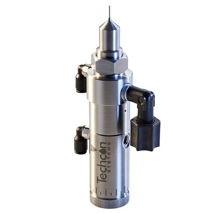
Size:104.1 x 25.4 mm (4.1” x 1.0”)
Weight:331g (0.73lb)
Liquid inlet:1/8” NPTInternal thread
Air intake:10-32 UNF-2B
Atomized air inlet:10-32 UNF-2B
Liquid pressure: maximum100 psi (6.9 bar)
Starting pressure: minimum70 psi (4.8 bar)
Liquid contact parts:303 Stainless steelDelrin®TheTeflon®
Cylinder material:303 stainless steel
Operating frequency: Exceeding 400 circle/branch
3.function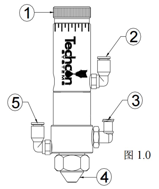
|
Project Number |
explain |
|
1 |
Stroke control adjustment knob |
|
2 |
Valve control inlet |
|
3 |
Liquid inlet |
|
4 |
Removable spray cap |
|
5 |
Atomized air inlet |
4. Valve connection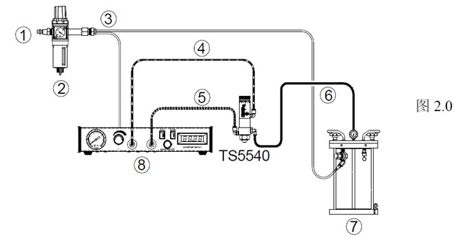
|
Project Number |
explain |
|
1 |
From air source |
|
2 |
Gas filter (optional) |
|
3 |
Constant airflow |
|
4 |
Valve air hose (provided) |
|
5 |
Atomizing air hose (provided) |
|
6 |
Liquid feed hose (optional) |
|
7 |
Liquid storage container(TS1258 -Purchase) |
|
8 |
Valve controller(TS500R -Purchase) |
5.Operating instructions
1.Set the valve air pressure of the valve controller to70 psi (4.8 bar).
2.Set the atomizing air pressure of the valve controller according to the viscosity of the spray liquid.
3.The liquid pressure of the liquid reservoir is set according to the viscosity of the spray liquid; Please do not exceed100 psi (6.9bar).
4. Place the waste bin under the valve nozzle and clean the valve until the liquid flows out steadily.
The coverage of spray is determined by the following factors:
? Stroke control adjustment - Clockwise rotation of the stroke control knob can reduce the liquid flow rate, while counterclockwise rotation will increase the liquid flow rate. Do not let the knob exceed the "line mark" on the knob seat.
The starting length set by the valve controller ("valve open" time)
? Liquid storage pressure
? Liquid viscosity
? Distance between nozzle and spray surface
6. Troubleshooting
|
fault |
Possible reasons |
Troubleshooting methods |
|
No liquid flow |
Liquid pressure too low |
Increase the liquid pressure of the liquid storage device |
|
The operating pressure is too low |
Raise the air pressure of the valve controller to70 psi |
|
|
Valve not working |
Check the valve pressure of the valve controller |
|
|
Liquid solidifies inside the valve chamber |
Remove the valve and thoroughly clean it |
|
|
Stroke control adjustment does not work |
Rotate the stroke control knob counterclockwise (do not exceed the "line mark") |
|
|
Unstable liquid flow |
Unstable liquid pressure |
Ensure a constant liquid pressure |
|
The operating pressure of the valve is too low |
Raise the valve operating pressure of the valve controller to70 psi |
|
|
The opening time of the valve is inconsistent |
Check the valve controller to ensure it provides stable air pressure output |
|
|
Gas is trapped in the valve cover |
Discharge gas from the valve |
|
|
After the valve is closed, liquid still flows out and stops after a period of time |
Gas is trapped in the liquid shield |
Discharge gas from the valve |
|
Spray interval is too short |
Increase the spray interval of the valve controller |
|
|
The liquid flows through the nozzle but does not |
The atomization pressure is too low |
Improve the atomization pressure of the valve controller |
|
Continuous dripping |
Nozzle andDelrin®The base is dirty |
Thoroughly clean the nozzle and base |
|
Delrin®The base is worn or damaged |
Replace worn or damaged parts |
|
|
Liquid pressure exceeds100 psi |
Reduce the liquid pressure in the liquid storage container until the dripping stops |
|
|
Valve installation error |
Remove the valve and reinstall it according to the instructions |
7. Maintenance and Cleaning
Required tools/Materials (one piece each): open-end wrench, retaining ring pliers, soft brushORing grease, wooden pin, andBig head screw(P/N=TSD1113-28); Recommended cleaning agent: isopropanol or similar solvent.
7.1 Thoroughly clean (see figure)3.0)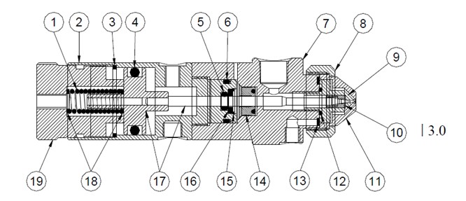
1. Release the liquid pressure from the liquid storage container.
2. Remove the liquid pipeline and valve air hose from the valve.
3. Adjust the stroke control knob(19)Rotate counterclockwise beyond the "line mark" and remove it, and the compression spring will push the knob out.
4. Remove the compression spring(1)And the Mylar washers at both ends(18).
5. Use an open-end wrench to remove the locking cap(8)Then, from the liquid shield(7)Pull out the air cap in the middle(11).
6. Use an open-end wrench to remove the nozzle(9)And gaskets(13); IfOThe ring is damaged, please replace it.
7. Grasp the liquid shield tightly(7)Rotate the cylinder counterclockwise/Needle assembly(2). After fully unscrewing, pull these two valve components straight apart to separate them.
8. Dip the soft brush in isopropanol and clean the liquid cover(7)Needles/Piston assembly(17)And the nozzle(9).
9. If the valve leaks, please use a large head screw(TSD1113-28)Remove the base(10)And replace the base with a new one; see also7.4 Instructions in section "Replacing the Base".
10. Turn the nozzle(9), gasket(13)Air cap(11)And the locking cap(8)Reinstall the liquid shield(7)In the middle.
11. Lubricate with greaseORing shaped(6)Then move the cylinder/Needle assembly(2)Reinstall the liquid shield(7).
12. First, place a Mylar washer on the needle/Piston assembly(17)Next, place another McLaren washer and compression spring into the stroke control adjustment knob in sequence(18)In this way, the compression spring can be installed(1).
13. Adjust the stroke control knob(19)Rotate clockwise fully into the knob base, then counterclockwise to the desired position, but do not exceed the "line mark" on the base.
7.2 Needle Replacement/Piston assembly and sealing ring (see figure) 3.0)
1. Execute the previous section (Section) 7.1 Steps in the section1 - 7.
2. IfORing shaped(6)Damaged, please replace it.
3. From the liquid shield(7)Remove the cup-shaped sealing ring(14).
4. Use retaining ring pliers to remove the first positioning ring(3).
5. Insert the needle/Piston assembly(17)From cylinder(2)Pull it straight out.
6. Use retaining ring pliers to remove the second positioning ring(15).
7. Remove the nylon gasket(16)andORing shaped(5); Replace damaged parts.
8. ReinstallORing shaped(5)Nylon gasket(16)And use a positioning ring(15)Fixed.
9. Reinstall the needle/Piston assembly(17)Using a positioning ring(3)Fixed.
10. Use a soft rod (such as a wooden pin) to seal the cup-shaped seal ring(14)Reinstall the liquid shield(7).
11. Execute the previous section (Section) 7.1 Steps in the section9 - 13.
7.3 Replacement of nozzle and air cap (see figure) 3.0)
1. Adjust the stroke control knob(19)Rotate counterclockwise beyond the "line mark" position and remove it.
2. Remove the compression spring(1)And the Mylar washers at both ends(18).
3. Use an open-end wrench to remove the locking cap(8)Then, from the liquid shield(7)Pull out the air cap in the middle(11).
4. Use an open-end wrench to remove the original nozzle(9)And gaskets(13).
5. Reinstall the gasket(13)And use an open-end wrench to reinstall the new nozzle(9)Please ensure thatOThe ring is installed on the nozzle; Do not tighten the nozzle too tightly.
6. Install a new air cap(11)Then use the locking cap(8)Fixed.
7.4 Replace the base (see figure) 4.0)
1. Insert the large head screw into the nozzle(9)Rotate clockwise until it aligns with the base(10)to be connected.
2. Use "soft claw" pliers to fix the nozzle, and then pull out the large head screw and sealing ring straight out.
3. Reinstall the new base on the head screw, and then insert the head screw into the nozzle in a straight line. To ensure proper alignment of the base, it is recommended to use a hand press to install the base.
